Bend Drawing
Make a Bend
Bend sheet metal to create highly functional parts at low cost (e.g. brackets, enclosures, etc.).
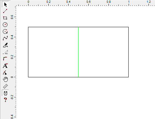
- Draw a 2D shape.
- Select the outermost lines and in the Z-Control, set the thickness.
- Draw a straight line where you want the bend.
- Select the straight line, and in the Line Type drop list, select Bend.
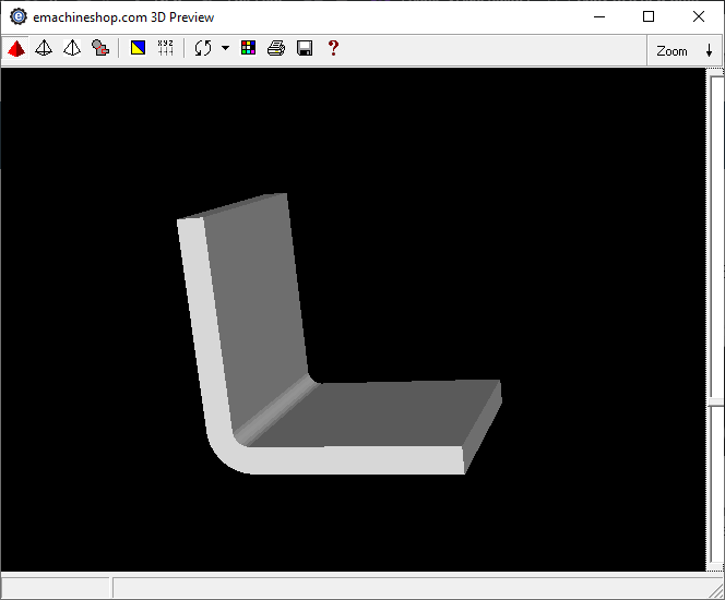
- To view the bend, choose View > 3D.
Adjust Bends
When specifying bends you may need to compensate for the distortion that occurs at the bend.
As an example, you might adjust bends to meet the desired dimension between two flanges.
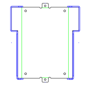
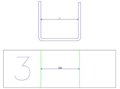
- Draw a shape with two parallel bend lines.
- Choose menu View > Model Bends.
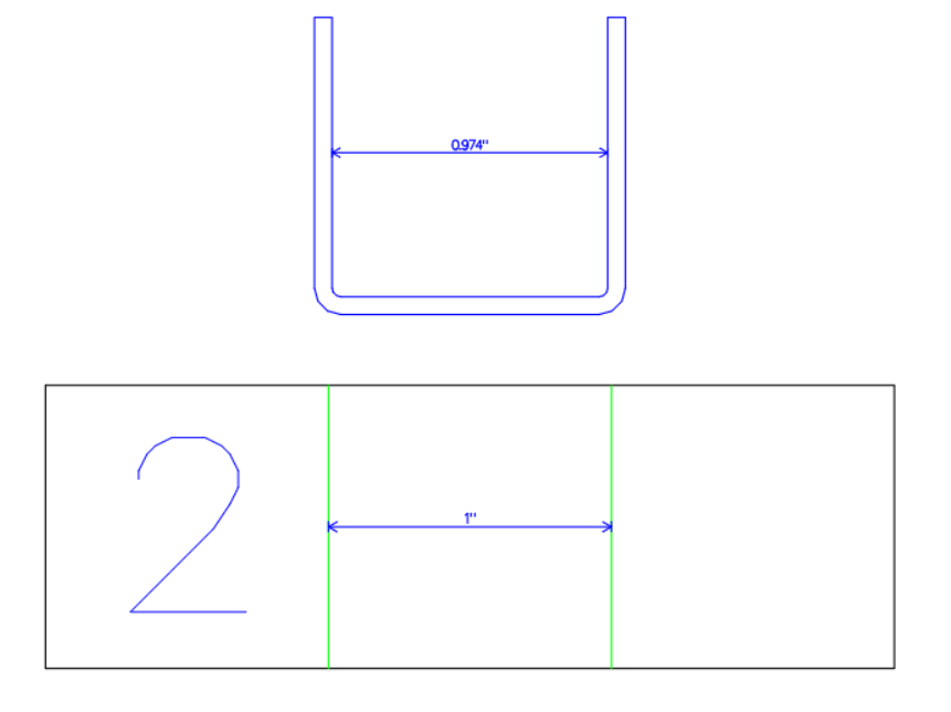
- Draw a straight line between the inside walls of the bend model and note the length.
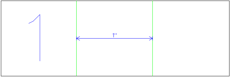
- Calculate the difference between the desired dimension and the length of the straight line.
- On your original drawing, draw a straight guideline between the bend lines.
- Add the computed value to the length of the guideline.
- Recenter the guideline if desired.
- Snap the bend lines to the ends of the guideline.
- Delete the guideline.
- Choose menu View > Model Bends and confirm the desired dimension.
Model and Fit Enclosures
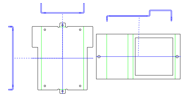
When making bends, you may need to fit two pieces of a part or enclosure together. Consider the following parts:
- Draw parts with bends that are intended to fit together.
- Create side views of the bends by choosing menu View > Model Bends:
- Rotate and slide the models on the screen to test the fit. In this example, notice the collision below:
- On the drawing, measure the amount of change needed and revise the design accordingly. Delete the original bend models and test the fit again. Notice how the fit has been corrected:
- Check the alignment of holes. Note below that the inside and outside holes (represented by the small rectangles) align.
- Here we are checking that the bottom section fits the bend shape of the top. It fits, but there is no allowance for tolerance. Adjust the design and recheck the Bend Model.
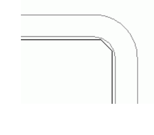
- On the left toolbar, use the Zoom tool to check all corners.


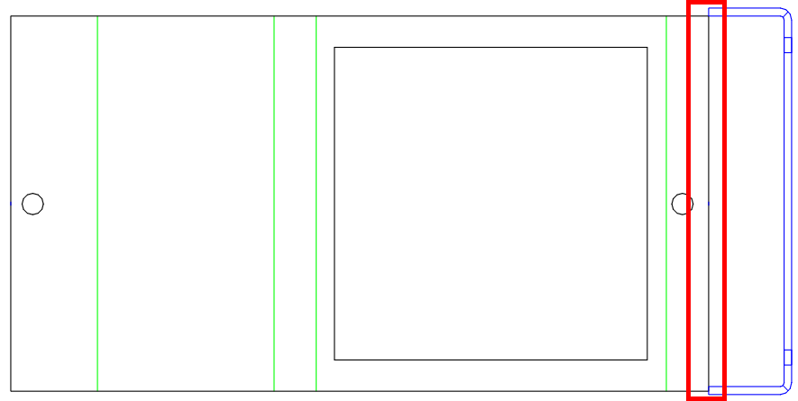
and insufficient overhang here:


Bend Tips and Limitations
- Provide for allowance. A loose fit is better than no fit.
- For two-part enclosures, add at least some overhang.
- Specify the radius of bends by choosing Job > Settings > Specifications: Bend.
- Avoid deep “U” shapes.
- Avoid several parallel bends that add up to more than 180 degrees.
- Avoid very complex bends that involve several bends at multiple angles.
- When possible, split complex designs into two or more parts that are bolted together.
Bend Specifications
The following specifications apply to bends via menu
- Linear Bend Position
Equal to the General Linear Tolerance, limits the variation of the position of the center of a bend.
- Angle Tolerance
Limits the variation of angle after bending to +/- 2 degrees.
- Radius of Bend Tool
Actual radius of the punch tool. The inside radius on the bent part may vary from the punch radius depending on thickness, material, etc.