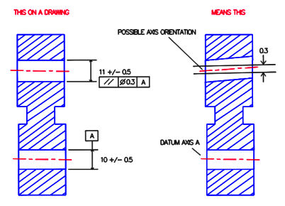
In mechanical part drawings, parallelism tolerance allows the designer to specify the degree to which a feature‘s orientation may vary with respect to its referenced datum by creating a tolerance zone parallel to that datum. The relevant feature, axis, or center plane must then lie within this zone. The parallelism symbol is generally used to ensure features are aligned for proper function.

In the left figure above, the boxed parallelism symbol and tolerance are used to control the center axis of a hole. The boxed symbols can be read “This axis must lie between two planes parallel to the axis A and spaced 0.3 apart”. Note that if the boxed tolerance includes a diameter symbol, indicating a cylindrical tolerance zone, the tolerance would apply to all views.
The tolerance zone created is indicated by the parallel lines in the rightmost figure, and applies for the entire length of the axis.
Parallelism is not often used in a tolerance stack except when it is applied to a surface, in which case it is treated like a flatness control since it refines the orientation of the surface.
