In GD&T, position is a versatile tolerance that can be used to control location, coaxiality, orientation or axis offset of a part feature or axis. Position tolerance is generally applied to features important to assembly like holes or slots, and it is often included when performing a tolerance stack.
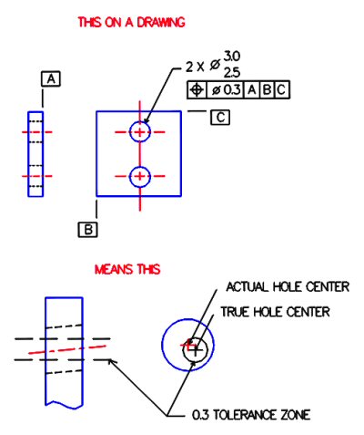
An example of position tolerance is shown below. The top figure shows the position symbol applied to two holes. The boxed symbols can be read "relative to datums A, B, and C, the position of these hole centers shall lie within a cylindrical tolerance zone of diameter 0.3".
The bottom figure shows an enlarged view of the upper hole. In side view of the part, the orientation of the hole is controlled in the same manner as perpendicularity or parallelism. In the top view, the position of the hole is controlled by its axis location. The actual position of the hole’s axis (shown in red) must lie within a tolerance zone related to the true axis position (shown in black) specified on the drawing. Note that in this example, both location and orientation are controlled simultaneously in 3D.
