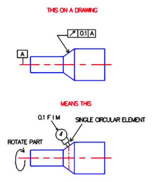
An example of runout tolerance is shown below. In the top figure the runout symbol is applied to the angled surface. The boxed symbols can be read “each circular element of this surface must have full indicator movement (FIM) of less than 0.1 relative to datum A”. The bottom figure shows a sample measurement taken at one cross section, but multiple measurements are required to verify runout. Note that the indicator is applied perpendicular to the measured surface, and that this tolerance controls only individual circular elements and not the whole surface simultaneously (see total runout).

